
Fellow

with maker adventurers Dr. Susan Klimczak, George Swallow & James Salvatore
gratitude for encouragement and assistance from our friends Per-Ivar Kloen and Jeannine Huffman
All the beautiful hand-drawn ATTiny85 illustrations are kindness of one of my favorite graphic artists of the maker movement, Marten Hazelaar from the great country of The Netherlands
The creative possibilities of the through-hole-type ATTiny85 microcontroller are awesome, if you know the basic characteristics, how to set one up, and how to write code. One cool introduction activity is a kinetic sculpture with LEDs and servo motors!
INTRODUCTION
Where might you have seen ATTiny85s before?
Well, ATTIny85s are all around us unseen!
They are used in alarm clocks, microwave ovens, washing machines, cameras, tablets, notebooks, mobile phones and refrigerators.
If you’ve seen a light show at a concert, it could have included ATTiny85s to point lights in the right direction, change color, and control brightness.
If you are a physical programmer, the Trinket (Adafruit) and the LilyTiny (Sparkfun via Leah Buechley), use the ATTIny85 as their microcontroller.
Why would an educator want to use one?
It’s inexpensive! They range from around $3 from Sparkfun to less than a dollar (in quantity, on auction) on eBay (need to have 3-6 week lead for shipping!). This is significant for our free program serving low income youth, because we can now afford to have youth make physical programming projects and take them home.
It’s small!! ATTiny85s are very small, but not so small that you can’t handle them. So using one can seriously shrink the size of any project and keep individual beginner projects to a manageable size.
It’s powerful! ATTIny85s are perfect for physical programming projects with just a few inputs/outputs because they can be programmed in the Arduino IDE. They accommodate digital (on or off) and analog (a value between 0 and 100% on) components, as well as servo motors.
THE BASICS
What is an ATTiny85?
An ATTiny85 is a microcontroller, which is a tiny computer designed to run small programs that can listen to or control electronic components that people connect to its “legs” (pins).
There are two types of ATTiny85s, through-hole types with legs and tiny surface mount types. This guide assumes the use of the through-hole type that is illustrated above!
The ATTiny85 program memory is flash memory, so when you remove power from the device, the program and data you have on it does not get erased; the next time you power up the ATTiny85 your code is still there, and runs as soon as the ATTiny is connected to power (a battery, USB port, or wall plug).
An ATTiny85 is a scaled down version of the main chip on Arduino Uno or Sparkfun Redboard development boards that you might be familiar with:

What’s on the ATTiny85 & how do you wire it in a circuit?
Wiring Diagram for ATTiny85:
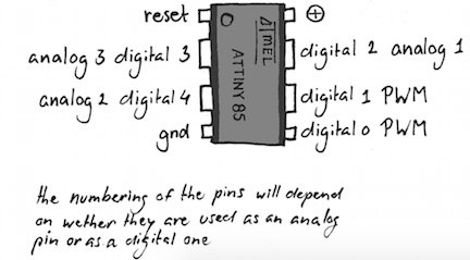
5 usable pins! There are 5 usable pins that can be set up as inputs or outputs. All of the pins can be used for digital components. Some can be used for analog components. For practical purposes, all 5 of the pins can be used for LEDs, buttons or servo motors.
Use with a socket! The through-hole ATTiny85 most conveniently sits in a socket so you can take it in and out when re-programming it. There are two kinds of sockets, but only one works well with ATTiny85 projects that require flattening out the pins (as we found out the hard way!).
This one with round legs and beads at the top doesn’t work well because the legs snap off when you try to bend them 90 degrees to solder them onto paper-based projects. However, they work fine for breadboard projects!
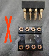
This kind with flat legs works well if you want to do a paper-based project where the legs need to be bent 90 degrees. You can buy these on Sparkfun for less than a dollar. However, they are even cheaper on eBay (just search “8 Pin DIL/DIP IC Socket” and you can get hundreds for a couple of bucks)

Line it up! The ATTiny85 needs to be lined up exactly the right way when you put it in any socket. It has a dot by the reset pin, which lines up with the notch on the socket.

Connecting to the computer for coding! To program the ATTiny85, an interface to a computer is needed. The easiest way to connect is by using a little board with a socket to plug in the ATTiny and the USB port to connect to the computer. The best ATTIny85 programmer we know and love is the Tiny AVR Programmer from Sparkfun and it has awesome tutorial and support!


The Tiny AVR Programmer can take code sent from the computer and load it into the proper locations in the ATTiny85’s program memory.
*****(there IS a way to program an ATTINY85 using an Arduino UNO here & here & here, but really, really, really, you want to get yourself the awesome little Sparkfun Tiny AVR programmer because it is designed to allow you to prototype projects directly on it)
SETTING UP YOUR ATTiny85 to talk to Arduino IDE
The best guide to setting up your Tiny AVR Programmer to talk to the Arduino IDE is through the Sparkfun Tutorial. However, it’s very detailed and it’s easy to get confused, so here is a barebones outline of what needs to be done:
1. Install Drivers for your Tiny AVR Programmer:
-
If you are using a PC computer, you will need to install these
-
No need for drivers if you are using Mac or Linux
2. Show Arduino IDE how to talk to and compile code for your ATTiny85
-
This works with Arduino IDE 1.6. XX or 1.8 XX
-
Make ATTiny appear as an option in your Arduino IDE Board Menu
Download add-on for ATTiny
Put it in your Arduino IDE Sketch Directory hardware folder
-
Be sure you plug your ATTiny + Tiny AVR Programmer in before you configure Arduino IDE (it doesn’t work if you don’t do this)
3. Configure Arduino IDE
-
Under Tools -->Board, choose “ATtiny85 (8MHz internal clock)”
-
Unlike when using an Arduino Uno or RedBoard, choosing a Serial Port is not necessary
-
With ATTiny85 (unlike with Arduino Uno or RedBoard), you do need to select a Programmer
Under Tools-->Programmer, choose USBTinyISP.
The Arduino ISP is an In-System-Programmer that is used to program
AVR microcontrollers. You can use the Arduino ISP to upload sketches
directly on the AVR-based Arduino boards without the need of the
bootloader.
4. When using a new ATTiny85, set the Clock Speed Once.
Do this by selecting Tools → Burn Bootloader once.
You are not really burning a bootloader, just setting clock speed!
Coding with the Arduino IDE
Coding with digital inputs and outputs. For digital inputs like buttons and digital outputs like LEDs and buzzers, the code will generally look exactly like it does for any standard Arduino-like microcontroller development board
Coding with SERVOs gets a little more complicated. So here is what you need to know and some sample codes we know and love for you to remix.
1. Servos can be used on any of the 5 digital pins 0-4
This is because the servo library code does its own pulse width modulation (PWM).
2. Using an alternate servo library is necessary with the ATTiny85
The standard Servo.h library does not work with the ATTiny85 because it relies on a 16MHz clock and the ATTiny85 uses an 8 MHz clock
The library that we have gotten to work best with servos is a modified version of the smaller SoftwareServo.h library (Here’s the info on SoftwareServo). My friend George Swallow modified the SoftwareServo library as SoftwareServo1, with some improvements that make coding the servos a little easier. Here’s where you can download either SoftwareServo or SoftwareServo1 libraries.
For using SoftwareServo library
You need to make a change to the original SoftwareServo library code because it was written for Wiring, the original IDE that was the basis for the Arduino IDE. So, in the first lines of the SoftwareServo.h
Change: #include <WProgram.h> to #include "Arduino.h"
If you don’t know how to load a library, Sparkfun has a great guide to loading libraries for both PCs and Macs.
After loading SoftwareServo onto the Arduino IDE, all you need to do is call it at the top of your sketch by using:
#include SoftwareServo.h
For using SoftwareServo1 library:
If you don’t know how to load a library, Sparkfun has a great guide to loading libraries for both PCs and Macs.
After loading SoftwareServo1 onto the Arduino IDE, all you need to do is call it at the top of your sketch by using:
#include SoftwareServo1.h
3. How does using the SoftwareServo1 library change the Servo code in sketches?
Example: here is a simple sketch with a servo named Tyrone that moves from 0 degrees to 179 degrees every 1.5 seconds or 1500 milliseconds. Below is both a comparison chart and an explanation.
The sketch can be copied and pasted from here to try it out.

At the beginning of the sketch: Change library
The name of the library needs to be changed to SoftwareServo1:
#include <SoftwareServo1.h> // include Software Servo1 Library
Inside void setup(): Modify servo parameters
The way that Arduino IDE servo libraries mathematically model PWM-type pulses is by assigning a “pulse width” that corresponds to a servo arm setting of 0 to 179 degrees. Software servo comes with defaults for 0 degrees at 544 microseconds and for 179 degrees at 2400 microseconds.
If you use the SoftwareServo1 (or SoftwareServo) library defaults with your servo, you may find that the servo “grinds” or vibrates strongly at 0 and 179 degrees. This means that the default settings are off for the type of servo you are using. The cheaper the servo --- and we used the cheapest microservos we could find --- the less precise they are.
If we modified the minimum and maximum pulse settings in the sketch, we found we could get rid of the grinding and vibrating. We found the “sweet spot” for the minimum and maximum pulse width through experimentation by using a sketch that moved the microservo arm position from 0 to 179 degrees. We modified the minimum and maximum pulse settings until there were no unusual vibrations.
For our microservos, we found that using the minimum and maximum pulse parameters of 496 and 2245 microseconds worked best.
Inside void loop(): Use a set of refreshes instead of a simple delay
When using the SoftwareServo1 (or SoftwareServo) Library, you cannot just use a simple delay command. It is necessary to “refresh” or update the servo reading at least once every 50 ms.
So for instance, if you want to move the servo from 0-179 degrees every 1.5 seconds with an Arduino, you MUST use the SoftwareServo::refresh() command every 50 milliseconds and do this 30 times to get to 1500 milliseconds (1.5 seconds).
So instead of using the normal IDE statement for an Arduino Uno,
delay (1500);
Use this “for loop”:
for(i=1; i<30; i++)
{
SoftwareServo::refresh();
delay(50);
}
Programming Sketch Samples
These are some “tried and true” ATTiny85 Arduino IDE sketches that use the SoftwareServo1 library. George Swallow and I commented them extensively so that others could understand and modify the example code, then be able to create their own code with ease.
Test Upload by Blinking OnBoard LED (click for link)
Sometimes it is useful for troubleshooting to check whether sketches are properly uploading to the ATTiny85. Remember to “burn bootloader” under Tools tab the first time you use your ATTiny85 to set the clock to 8Mhz internal. Then try uploading this sketch to see if you can blink the onboard LED
ONE SERVO MOTOR!
Controlling One Servo Motor: Servo Motor arm switches 0 & 179 degrees every 1.5 seconds (click for link)
This is the link to the example sketch for controlling one servo motor. Of course, you can remix it to have the servo motor “flip flop” or switch between any two positions. You can also remix the time between “flip flops” or switches.
Controlling One Servo Motor: Servo Motor arm sweeps smoothly back & forth between 0 and 179 degrees every 1.5 seconds (click for link)
Sometimes you want to servo arm to sweep smoothly instead of jerking back and forth between two positions. This is the link to an example sketch for sweeping one servo motor.
ONE SERVO MOTOR + BLINKIE LED!
Controlling One Servo Motor + One LED: Servo Motor arm SWITCHes 0 & 179 degrees every 1.5 seconds + LED blinks every second. (click for link)
This is the link to the example sketch for controlling one servo motor + one LED. To change the LED blinking time, you must change the function “RefreshBlinkie” at the end of the sketch and do the maths to get the timing to work with the servo refresh timing.
Controlling One Servo Motor + One LED: Servo Motor arm SWEEPS smoothly between 0 & 179 degrees every 1.5 seconds + LED blinks every second (click for link)
Sometimes you want to servo arm to sweep smoothly instead of jerking back and forth between two positions. This is the link to an example sketch for sweeping one servo motor AND blinking an LED. To change the LED blinking time, you must change the function “RefreshBlinkie” at the end of the sketch and do the maths to get the timing to work with the servo refresh timing.
TWO SERVO MOTOR
Two Servo Motors sweep smoothly in opposite directions (between 0-180 degrees & 180-0 degrees) (click for link)
This example code sweeps two servo motors smoothly in opposite directions. They sweep from 0-180 degrees / 180-0 degrees. There are variables to control the beginning and ending degrees of servo sweep, as well as the rate of how fast the servos will sweep.
Making with the ATTiny85
George, James and I spent nearly a year experimenting with ATTiny85s to create this guide because we could not find a beginner-friendly guide on the internet that was useful for maker educators who wanted to use servos. We hope you find this guide helpful and will add comments to make it better.
You can find a downloadable googledoc of this guide here.
We have been experimenting with using ATTiny85s in a kinetic sculpture activity inspired by the work of Jeannine Huffman and the work of Per-Ivar Kloen & Marten Hazelaar. We are using vinylcut copper circuit traces (using Per-Ivar's design) and remixing the kinetic sculpture panda (from Jeannine Huffman). We added 3D print diffusers for the LEDs to inject a little fun! A future blogpost will document the activity plan for kinetic sculptures using street art as an inspiration, but here are a few videos of our experiments to inspire you!


